⚡ Storm or Roof Damage? Get a FREE Estimate
Text ESTIMATE to (844) 907-2546
Or call (800) 792-0212 for 24/7 emergency response
AI-powered • No obligation • Licensed IL & WI
Insulated Concrete Forms (ICFs) represent a modern, efficient, and durable construction method that is revolutionizing how we think about building energy-efficient and disaster-resistant homes and buildings. Here’s a breakdown of what ICFs are, their benefits, installation process, and why they might be the right choice for your next construction project.
Technical Description
- ICFs consist of hollow blocks or panels made from rigid foam insulation. These blocks are stacked to form the walls of a building, then filled with steel-reinforced concrete.
- The foam acts as a thermal blanket, significantly reducing heat transfer and providing excellent insulation.
- This construction method reduces the need for traditional wood framing, adding to its environmental benefits.
Alternate Terms
- Quiet ICF Wall
- Energy-Saving ICF Wall
- Advanced ICF Technology
- ICF Precision Wall System
- Moisture-Control ICF Wall
- Disaster-Resistant ICF Wall
- ICF Thermal Blanket
Choosing ICF construction means investing in reduced energy loss, enhanced indoor comfort, and peace and quiet. It’s an opportunity during construction to ensure high-quality, durable, and energy-efficient living spaces.
Scope
- ICFs provide a comprehensive solution by offering insulation, air sealing, a drainage plane, and structural strength without thermal bridging.
- Proper installation according to manufacturer’s guidelines ensures a continuous air barrier and optimal performance.
Description
- ICF walls boast higher R-values and airtightness compared to traditional stick-frame constructions, thanks to the continuous insulation and minimal thermal bridging.
- Different types of ICF systems cater to various architectural needs, from flat to waffle-grid walls, ensuring flexibility in design.
How to Install ICFs
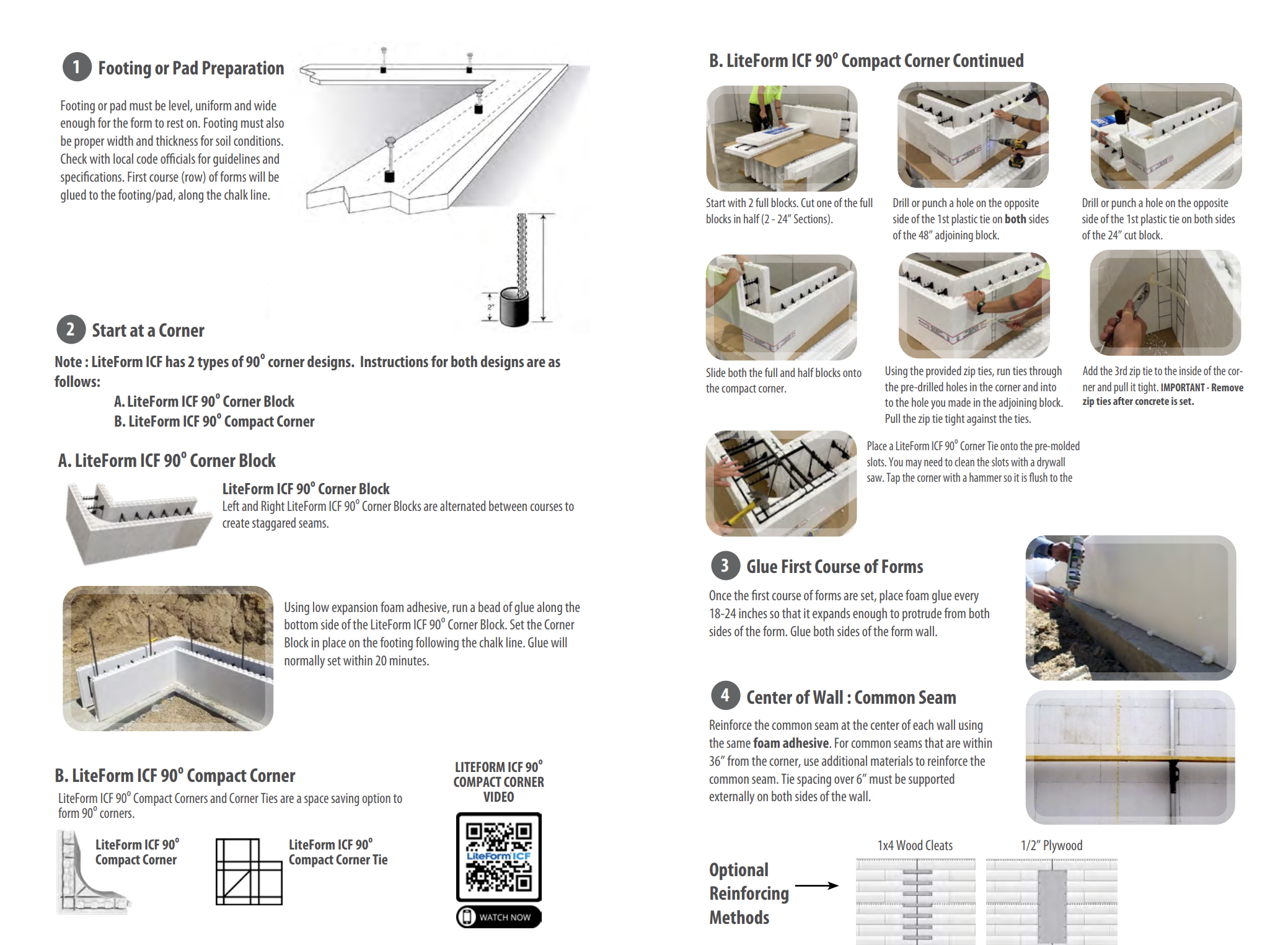
- Preparation:
- Place dowels (rebar) in footings, foundation wall, or slab as required.
- Set up temporary braces along the first course to align the ICF forms and prevent movement.
- Initial Stacking:
- Set blocks on concrete footings, even if recently placed and uncured.
- Place termite shield.
- Complete one course all the way around the building’s perimeter.
- Stagger subsequent courses to avoid aligning vertical foam joints from one course to the next. Ensure vertical and horizontal cavities line up and set horizontal and vertical rebar as required.
- Cut openings as needed, either during construction or after the entire wall is built.
- Install bucks (2×4 or 2×6 wood framing) around windows and doors to serve as an attachment surface. Use pressure-treated wood for window framing and all other wooden structural components or prefabricated plastic/vinyl bucks.
- Additional Steps:
- Place intermediate floor connections and supports.
- Install sleeve penetrations for various services such as dryer vents, electrical, HVAC, cable, telephone, solar, plumbing, outside fixtures, and outlets.
- Locate and mark block beam pockets.
- Reinforce and support the block brick ledge if applicable.
- Bracing:
- Brace the wall forms every 6 feet with strong temporary bracing to ensure they stay level, plumb, square, and straight during the concrete pour and to support the weight of the concrete until it achieves the desired strength.
- Bracing is needed at corners, window and door openings, periodically along the length of walls, and at the top of the forms. Window and door bucks are braced inside horizontally and vertically.
- Top braces square the forms and provide a surface to check wall height and cut uneven blocks. Follow the manufacturer’s recommendations completely.
- Place anchor bolts and ledgers as required for floor system attachment. Options include ledgers, pockets, embedded joist hangers, or direct bearing. Ledgers may be made of pressure-treated wood or installed with a water-resistant membrane.
- Bolts and ledgers are placed before the pour, with foam cutouts around bolts to allow concrete to back up the ledger. Embedded joists require cutting out the foam and inserting wood spacers before the pour to create a pocket in which to seat the joist. Some code authorities also require the embedded joist to be fire-cut. Refer to details provided by the manufacturer.
- Service Sleeves:
- Place sleeves for any services such as wiring and piping.
- Foam Seal Joints:
- Foam seal joints, possibly per course, to secure blocks until concrete is poured and to maintain airtight construction.
Pre-pour Checklist
- Confirm the concrete order with the dispatcher.
- Ensure the correct amount of concrete is ordered, with specified mix design and slump.
- Order a second truck to be shipped when called and space subsequent trucks at 45-minute intervals.
- Inform the supplier that the order will be pumped for an ICF wall and reject trucks with more than a 6.5” slump.
- Collaborate with the ready-mix supplier to meet ICF concrete specifications.
- Choose appropriate concrete pouring equipment, such as line pumps or boom pumps.
- Ensure a steady pour rate and be cautious of overhead power lines.
- Manage the pour by checking each new truck’s concrete slump, having adequate manpower, and proper equipment.
Choosing Concrete Pouring Equipment
When deciding on the appropriate equipment for concrete pouring, consider the following factors:
- Line Pump vs. Boom Pump:
- Line Pump (Trailer Pump):
- Requires manual movement and lifting of the hose.
- More labor-intensive.
- Lower hourly rates but may incur similar total costs due to longer setup, pumping, and takedown times, as well as increased manpower requirements.
- Boom Pump:
- Faster completion if adequately prepared.
- Specified by reach (e.g., 28, 32, or 36 meters).
- Commonly used for residential jobs.
- Line Pump (Trailer Pump):
- Hose Width and Attachments:
- Reduce hose width to at least 3 inches for efficient pouring.
- Utilize attachments such as elbows or rams horns at the hose’s end to break the fall and collect concrete.
- Pouring Techniques:
- Maintain a steady pour rate without pulsing or stopping and starting.
- Aim for approximately 20 minutes to pour 8 yards of concrete.
- Safety Considerations:
- Be vigilant of overhead power lines, particularly when using boom equipment.
- Consult with the pump company and request utility company assistance to shield lines during the pour, especially under specific temperature and humidity conditions where electricity transfer risks are heightened.
Managing the Pour
- Check Concrete Quality:
- Inspect the concrete in each new truck upon arrival to ensure the slump is correct.
- Communicate with the pump operator and ready-mix drivers that no water should be added without your approval.
- Remember that a wetter mix may ease their job but can compromise quality. Decide whether to send back overly wet concrete or wait for it to tighten up.
- Readiness for Pouring:
- Be prepared to pour as soon as the trucks arrive.
- Ensure adequate manpower is available as pump days can be demanding. Do not skimp on personnel.
- Manpower Requirements:
- For Boom Pump:
- 1 pump operator
- 1 hose man
- 2 wall watchers (inside and outside)
- 1 utility person for emergencies and contingencies
- For Line Pump:
- 1 pump operator
- 1 hose man
- 1 outside wall watcher
- 2 or more hose handlers, rolling scaffolding crew, or wall watchers
- For Boom Pump:
- Equipment Preparation:
- Equip your team with the necessary tools for a smooth operation.
- Ensure everyone has proper personal protective equipment (PPE) such as gloves, hardhats, eye protection, long-sleeved shirts, and long pants.
- Have tools like slump cones, brooms, trowels, shovels, and rinsing water readily available.
Pouring the Concrete
- Prepare Scaffolding:
- Ensure scaffolding or walk boards are correctly installed and safe for use.
- Adjust the height of the scaffolding so that the hose man is standing at approximately waist height to the top of the wall. This minimizes fatigue and allows for better visibility.
- Continuous Adjustment of Scaffolding:
- Continually raise the scaffolding as foam brick courses are added to allow the pour man to see both sides of the wall during the pour.
- Assistance for Hose Man:
- Assign a second person to assist the hose man, informing them of the concrete’s location in each section and when to move.
- Strategic Filling Technique:
- Start filling below a window or near a corner with a window within 4 feet for visibility of mix and slump.
- Avoid placing concrete directly into corners.
- Move towards the window, allowing concrete to fill up to the bottom of the window, then switch to the other side of the window, starting approximately 4 feet away, and fill back towards the window to lock in the other side.
- Consider pumping the first yard back into the ready-mix truck and blending it with the remaining concrete for consistency.
- Plan for Lifts:
- Aim to surpass the 32-inch level (above the seam of the second course of forms) with the first lift.
- Most houses, up to a 12-foot wall height, will require three passes for complete fill.
- Maintain Cleanliness and Avoid Void Formation:
- Have someone trail the hose man to scrape and shake off any concrete buildup on the top of the forms or rebar to prevent voids.
- Fill the Walls Strategically:
- On the second pass, avoid filling too close to the top; stay at least 24 inches down from the top course.
- Do not fill over doors and windows until the last pass.
- Exception: On deep lintels (over 32 inches), pour a small amount to begin forming the lintel and loading the window.
- Final Pass and Slump Adjustment:
- For the last pass to the top of the wall, consider increasing the slump by adding water.
- Tap or vibrate the outside of the wall for proper consolidation, especially over lintels where extra rebar and stirrups can prevent good compaction.
Fixing Blowouts
- Prevention is Key:
- Pay close attention during pouring to prevent over-pouring and bulges, which can lead to blowouts.
- Be mindful of damaged foam areas and avoid excessive water in the cement mix, as these factors contribute to blowouts.
- Repair Process:
- Clean up any spilled concrete and gather broken foam pieces from the blowout.
- Place the broken foam pieces back into the wall, ensuring they fit snugly into the damaged area.
- Covering the Damaged Area:
- Cut a piece of half-inch OSB to cover the damaged area, ensuring it adequately covers the blowout.
- Securing the OSB:
- Screw the OSB piece to the furring strips surrounding the blowout area.
- For larger blowouts, place OSB pieces on both sides of the wall at the location of the blowout.
- Clamp the OSB pieces in place with a threaded bar inserted through the wall and both pieces of OSB.
Performing Final Inspection and Cleanup
- Thorough Inspection:
- Conduct a comprehensive inspection of the job site to ensure nothing has been overlooked.
- Check for any missed areas or incomplete tasks.
- Check for Wall Movement:
- Examine the walls to see if there are any signs of movement.
- Address any bowing or shifting promptly, as early detection makes correction easier.
- Assess Fill Quality:
- Confirm that the walls are adequately filled with concrete.
- Cross-check the estimated yardage required for the walls with the load tickets to ensure accuracy.
- Determine if there is any excess yardage remaining, as having a surplus is preferable to bringing back additional concrete later.
- Verify Key Locations:
- Check door threshold locations to ensure they have not been overfilled.
- Verify that all beam pockets have been properly filled to prevent issues later on.
- Address Issues Promptly:
- Take immediate action to rectify any discrepancies or oversights identified during the inspection.
- Remember that it is easier to address issues today rather than waiting until tomorrow when concrete may have set.
Installing Utilities and Attaching Cladding
- Install wiring and plumbing after concrete pouring, covering with metal plates.
- Apply waterproofing on exterior sub-grade structures to prevent water intrusion.
- Install waterproofing on below-grade portions of the ICF.
- Attach interior drywall and exterior cladding finishes using metal or plastic ties embedded in the foam.
Ensuring Success:
- Utilize experienced ICF construction crews to ensure proper installation and handling.
- Pre-pour inspections and adherence to best practices are crucial for a successful build.
- Accommodate climate considerations, especially in cold weather, to ensure concrete cures correctly.
Applications and Benefits:
- Energy Efficiency: ICFs significantly reduce heating and cooling costs by maintaining consistent indoor temperatures.
- Disaster Resilience: The structural integrity of ICF buildings offers superior resistance to tornadoes, hurricanes, and fires.
- Sound Insulation: ICF walls dramatically reduce exterior noise, creating a peaceful indoor environment.
- Sustainability: Reduced reliance on wood and enhanced energy efficiency make ICF a green building choice.
Installation Tips:
- Precision in stacking and bracing is key to maintaining the integrity of the ICF wall system.
- Ensure seamless integration of windows, doors, and utilities by following detailed installation guides for framing and service penetrations.
- Regular inspection and adjustments during the pour are essential to prevent structural issues.
Addressing Climate and Seismic Challenges in ICF Construction

- Climate Considerations for ICF Construction:
- When pouring concrete in below-freezing conditions, accommodations such as heated enclosures or admixtures to prevent freezing are necessary.
- Concrete within ICF forms cures more slowly and remains hydrated, resulting in a stronger final structure.
- Seismic Considerations for ICF Construction:
- In earthquake-prone areas, buildings must be constructed with appropriate seismic protections to ensure safety and integrity.
- Reinforcement of all ICF walls is required across all Seismic Design Categories to enhance durability and resilience against seismic activity.
Compliance with Building Codes and Programs
ENERGY STAR Single-Family New Homes, Version 3/3.1 (Rev. 11):
- Rater Field Checklist:
- Thermal Enclosure System: Key focus on reducing thermal bridging with options such as Structural Insulated Panels, Insulated Concrete Forms, and Double-wall framing among others. (Section 3, specifically 3.4)
- Exemptions:
- Mass walls in passive solar designs are exempt from thermal bridging requirements under specific conditions. (Footnote 17)
- Up to 10% exemption for total exterior wall surface area from thermal bridging requirements for intentional design details. (Footnote 18)
- Definition and requirements for double-wall framing outlined. (Footnote 21)
DOE Zero Energy Ready Home (Revision 07):
- Exhibit 1 Mandatory Requirements:
- Homes must be certified under ENERGY STAR Qualified Homes Program. (Exhibit 1, Item 1)
- Insulation levels must meet or exceed 2015 IECC levels with Grade 1 installation per RESNET standards. (Exhibit 2, Item 2)
2009, 2012, and 2015 International Residential Code (IRC):
- General ICF Provisions:
- ICFs are addressed in the IRC, specifically Section R611 (R608 in 2015, 2018 editions).
- Maximum Story Heights: Maximum story heights and unsupported wall heights for ICF walls specified. (Section R301.3)
- Seismic Provisions: Outlines seismic requirements for various design categories. (Section R301.2.2)
- Limitations Based on Wind Speed and Seismic Design Categories: Specifies limitations on ICF use based on design wind speed and seismic design categories. Buildings outside specified scopes require design according to PCA 100 or ACI 318.
2015, 2018, and 2021 IRC:
- ICF Requirements: Additional requirements for ICF systems including maximum design wind speed limits and applicability based on Seismic Design Categories. (Section R608)
- ASTM E2634 Compliance: Flat ICF wall system forms must adhere to ASTM E2634 standards.
Retrofit Standards:
- Code for Additions, Alterations, or Repairs: Requirements for renovations conform to current codes without necessitating full compliance for unaltered portions. (Section R102.7.1)
- Appendix J: Regulates repair, renovation, alteration, and reconstruction of existing buildings for safe continued use.
ASTM Standards:
- ASTM E2634-11: Standard Specification for Flat Wall Insulating Concrete Form (ICF) Systems. Applies to ICF systems serving as permanent formwork for concrete. Specifies the ICF Systems should result in a uniform monolithic concrete core for various structural components.
Important Compliance Highlights:
- Compliance with ENERGY STAR and DOE Zero Energy Ready Home signifies adherence to advanced energy efficiency standards.
- IRC sections detail structural requirements, seismic provisions, and limitations for ICFs to ensure safe and resilient construction.
- ASTM E2634-11 sets forth specifications for flat wall ICF systems, underscoring the importance of uniform concrete cores for structural integrity.
- Retrofitting standards provide flexibility for upgrading existing buildings with modern ICF technologies while respecting the historical or existing structural integrity.
ICF construction is not just about building walls—it’s about creating safer, more comfortable, and energy-efficient spaces. Whether for residential or commercial projects, ICFs offer a compelling alternative to traditional construction methods, aligning with modern sustainability and efficiency goals.
For immediate service or consultation, you may contact us at Allied Emergency Services, INC.
Contact Information:
- Phone: 1-800-792-0212
- Email: Info@AlliedEmergencyServices.com
- Location: Serving Illinois, Wisconsin, and Indiana with a focus on the greater Chicago area.
If you require immediate assistance or have specific questions, our human support is readily available to help you.
Disclaimer: This article is intended for informational purposes only. For professional advice, consult experts in the field.
⚡ Need Storm Damage Help? We Serve 155+ Cities
Allied Emergency Services provides 24/7 emergency restoration across Illinois, Wisconsin, Indiana, and Michigan. Text ESTIMATE to (844) 907-2546 for a free estimate in minutes.
Top service areas: Chicago • Naperville • Aurora • Kankakee • Joliet • Rockford • Schaumburg • Milwaukee • Madison • We’re Hiring!
⚡ Storm or Roof Damage? Get a FREE Estimate
Text ESTIMATE to (844) 907-2546
Or call (800) 792-0212 for 24/7 emergency response
AI-powered • No obligation • Licensed IL & WI
Need storm restoration and roofing help?
Allied Emergency Services — Licensed IL & WI Storm Restoration And Roofing Specialists
For 27 years, Allied has been serving Illinois and Wisconsin homeowners with storm restoration and roofing across Illinois and Wisconsin. IICRC-certified, EPA Lead-Safe, IL Licensed Roofing Contractor #104.019029. 24/7 emergency response.
Learn about our Storm Restoration And Roofing service →Free property assessment within 24 hours · No obligation · Insurance claim support